Showing posts with label math. Show all posts

Tuesday, March 3, 2020

Quaternion Exponentiation

For instance I have 45 degree rotation quaternion p. and if I take p ^ (1/3) then I'll get 15 degree rotation quaternion. This is geometric interpretation of quaternion exponentiation use case.

Let say I have q^(1/3) which is 1/3 power of quaternion q.

Mathematically we can define

log q = [0 alpha*n], n is the rotation axis.

exp q = [cos(alpha) n*sin(alpha)], alpha is the rotation angle.


Quaternion Exponentiation is defined down below.

q^(t) = exp(t log q)


Quaternion QuaternionExp(Quaternion q, float t)
{
    Quaternion newQ = q;

    float currentAngle = Mathf.Acos(newQ.w);

    // At the moment newQ's x, y, z has normal and already applied sin(w)

    // q' = exp(t * log q)
    // log q = [0 alpha*n]
    // exp p = [cos(alpha) n*sin(alpha)]

    float newAngle = currentAngle * t; // cos(alpha) term
       
    // what / Mathf.Sin(currentAngle) does is extract normal vector from the appllied nx, ny, nz
    float newX = newQ.x / Mathf.Sin(currentAngle) * Mathf.Sin(newAngle);
    float newY = newQ.y / Mathf.Sin(currentAngle) * Mathf.Sin(newAngle);
    float newZ = newQ.z / Mathf.Sin(currentAngle) * Mathf.Sin(newAngle);
       
    newQ.x = newX;
    newQ.y = newY;
    newQ.z = newZ;
    newQ.w = Mathf.Cos(newAngle);

    return newQ;
}

QuaternionExp is the implementation of Quaternion Exponentiation in C#.

Like I mentioned that we have 45 degree rotation quaternion q.

Quaternion q = Quaternion.Euler(0, 45, 0);

and 1/3 degree of 45 is 15 degree so if I take q^(1/3) then I'll have 15 degree rotation quaternion and I can apply it to gameobject.


Quaternion q = Quaternion.Euler(0, 45, 0);

// q is the 45 degree rotation.
// q^(1/3) will be 15 degree rotation.       
q = QuaternionExp(q, 1.0f / 3.0f);
       
this.transform.localRotation = q;


Last thing I want to describe is why we took / Mathf.Sin(currentAngle) when we calculate newX, newY, newZ.

This is because newQ's x, y, z values are already applied sin(theta) which we needed to extract from the value. so we divide Sin(currentAngle) from all of the newQ's x, y, z and apply Sin(newAngle).

That's all!


Sunday, March 1, 2020

Ray Marching


Ray Marching
2020-02-24
Kiyoung Moon

Basics
Ray Marching is a kind of ray tracing algorithm. I couldn’t see any case where it is used without SDF(Signed Distance Function).

SDF(Signed Distance Function) is a distance function which means we represent shapes with the function instead of vertices data. For instance, we have sphere, which has radius ‘r’.


If we define ‘e’ is a position of camera, we can define sphere like below.


If the function f(x,y,z) is positive then camera ‘e’ is outside of the sphere.
If the function f(x,y,z) is 0 then camera ‘e’ is on the surface of the sphere.
If the function f(x,y,z) is negative then camera ‘e’ is inside of the sphere.

We can use this value in the Ray Marching algorithm.


Ray Marching
Like I said, Ray Marching works with SDF. It will not test (collision test) with the mesh data which is vertices.

Every shapes in the Ray Marching uses SDF shapes. You can see some of primitive SDF shapes down below.


There are many primitive SDF shapes that people already discovered. You can visit iq’s website. (https://www.iquilezles.org/index.html)

What is ray marching?
First, we need a Ray. We shoot the Ray into the screen and then checks whether there are any shapes that is collide or not. Instead of using traditional collision detection logic, we can use SDF. Assume we have E which is the position of the Ray.


The start position of Ray is E. and we can check whether it is collided with sphere or not. If not then we can go forward. How much? Can we go 0.001 more? 0.01 More?
Of course, we can go 0.00000001, which is small step. It is working. Do we have any problem here? Yes. It is slow!

Now we can use SDF and can save our time. As you can see, there are three spheres and we can get the distances using this equation.


As use can see, red line is the shortest distance.


‘r’ is the radius of sphere 3(see the number inside of sphere). If we take ‘D – r’, this is the safe distance that Ray Marching algorithm can use for their step. What is the means of safe distance?

Like I shown that we could take small step which is 0.0001 for Ray but it is too slow and it is useless to check whether collision happen or not. If we take safe distance then we can move Ray quickly.

After we use safe distance for the Ray’s step then next Ray position is going to be Blue point on the Ray’s direction like below image.


Ray Marching algorithm keep moving forward until it reaches sphere or end of maximum ray distance. If Ray reaches to the end of maximum ray distance then it means there is no collision happen so pixel color will be black.

If we found collision then we can use this color of sphere.


float4 CalculateScene(float3 eye)
{
        float globalDst = maxDst;
        float3 colour = float3(0,1,0);

        // iterate all the shapes to check the distance.
        for (int i = 0; i < numShapes; ++i)
        {
               Shape shape = shapes[i];
               float distance = GetShapeDistance(shape, eye);

               // closer
               if (distance < globalDst)
               {
                       colour = shape.colour;
                       globalDst = distance;
               }
        }

        return float4(colour, globalDst); // w is the distance      
}


while (rayDst < maxDst) {
        marchSteps++;
        float4 sceneInfo = CalculateScene(ray.origin);
        float dst = sceneInfo.w;

        if (dst <= epsilon) {                
               Result[id.xy] = float4(sceneInfo.xyz, 1);
               break;
        }

        ray.origin += ray.direction * dst;
        rayDst += dst;
}

This is the result image.


Wednesday, February 26, 2020

Wrapping angle

Because nature of rotation angle, when we interpolate angles we could have some problems. For instance we have angle A0 and A1.

A0 is -170 degree
A1 is 170 degree

If we interpolate A0 to A1 then it will take 340 degree turn to reach the A1.(which is clockwise)

instead we can take 20 degree which is counter-clockwise, it is much faster way to reach A1. To solve this kind of problem we can use wrap angle technique.


// angle in degree
float wrapPI(float angle)
{
float secondTerm = floor((angle + 180.0f) / 360.0f);
return angle - 360.0f * secondTerm;
}

floor is the function which will take same as given input x or highest integer value less than.

As you can see the below video, blue line is the A0(which is base angle) and red line(longer one) is the target angle which is A1. shorter red line is the result of interpolation.


// angle in degree
float wrapPI(float angle)
{
float secondTerm = floor((angle + 180.0f) / 360.0f);
return angle - 360.0f * secondTerm;
}

float baseAngle = 0;
float targetAngle = 90;
float angleRatio = 0.0f;

void Render(HDC hdc)
{
XFORM xForm;
xForm.eM11 = (FLOAT) 1.0;
xForm.eM12 = (FLOAT) 0.0;
xForm.eM21 = (FLOAT) 0.0;
xForm.eM22 = (FLOAT) -1.0;
xForm.eDx = (FLOAT) 300.0;
xForm.eDy = (FLOAT) 300.0;

SetGraphicsMode(hdc, GM_ADVANCED);
SetWorldTransform(hdc, &xForm);

float baseLength = 100;
float targetLength = 80;

float diffAngle = wrapPI(targetAngle - baseAngle);
float angle = baseAngle + (diffAngle * angleRatio);
// draw baseAngle
HPEN bluePen = CreatePen(PS_SOLID, 1, RGB(0, 0, 255));
HPEN redPen = CreatePen(PS_SOLID, 1, RGB(255, 0, 0));
HGDIOBJ oldPen = nullptr;

oldPen = SelectObject(hdc, bluePen);
MoveToEx(hdc, 0, 0, nullptr);
// convert degree to radian
float baseRadian = baseAngle * 3.14 / 180.0f;
LineTo(hdc, cosf(baseRadian) * baseLength, sinf(baseRadian) * baseLength);

SelectObject(hdc, oldPen);
DeleteObject(bluePen);
oldPen = SelectObject(hdc, redPen);
MoveToEx(hdc, 0, 0, nullptr);

float angleRadian = angle * 3.14 / 180.0f;
float targetRadian = targetAngle * 3.14 / 180.0f;
LineTo(hdc, cosf(targetRadian) * baseLength, sinf(targetRadian) * baseLength);

MoveToEx(hdc, 0, 0, nullptr);
LineTo(hdc, cosf(angleRadian) * targetLength, sinf(angleRadian) * targetLength);
SelectObject(hdc, oldPen);
DeleteObject(redPen);

angleRatio += 0.01f;

if (angleRatio >= 1.0f)
{
// choose another
baseAngle = rand() % 360;
targetAngle = rand() % 360;
angleRatio = 0.0f;
}
}


Monday, February 24, 2020

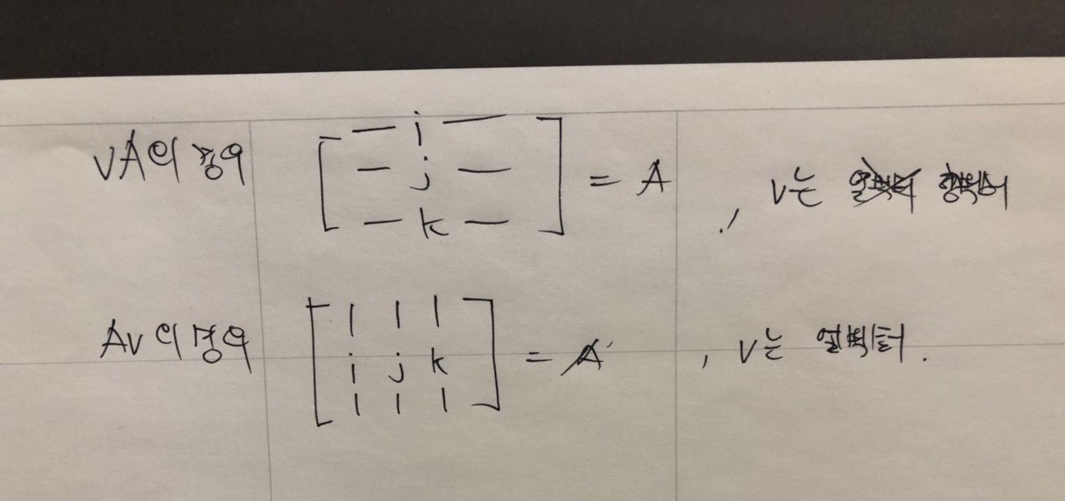
Representation of basis vector in matrix form.

When you read math books related with game programming, you should know representation of basis vector is depends on representation of vector form.

if the book uses row vector then vector multiplication with matrix is going to be
vM form which is above form in the below image.


if the book uses column vector then vector multiplication with matrix is going to be Mv form which is below form in the above image.

Representation of basis vector i, j, k are also depends on the order of vector representation like the image I shown.


Sunday, February 2, 2020

v' = vRT

when we use row vector v then applying matrix multiplication.

vRT

Rotation matrix R will be applied first and then T will be applied.
Order that the matrices are multiplied, from left to right.

Sunday, December 15, 2019

Representation of linear transformation of matrix

Let say there is a 3x3 matrix

[m11 m12 m13]
[m21 m22 m23]
[m31 m32 m33]

[m11 m12 m13] is a row vector

[m21 m22 m23] is a row vector

[m31 m32 m33] is a row vector

and which of above are basis vectors in 3D space. i, j, k in standard form.

[m11 m12 m13] is a row vector and i

[m21 m22 m23] is a row vector and j

[m31 m32 m33] is a row vector and k

using linear transformation we can write a vector v like down below.

v = vx*i + vy*j + vz*k

if we apply some transform(matrix) into vector V and we can visualize it.

for instance we have 

[1 0 0]
[0 1 0] == matrix A
[0 0 1]

it is an identity matrix and if we multiply vector v with matrix.

vA

we will get v because A is an identity matrix.

if matrix A is like down below.

[0.75 0.75 0]
[0 1 0]
[0 0 1]

vector v or shape of model will be scaled, shrink.


Using this representation, we can guess what the shape will look like when we apply some transformations. (Sorry! I'm not good at drawing)

Representation of vector and multiplication.

There are two ways to represent of vector.

row vector and column vector.

[x y z] is a row vector

[x]
[y]
[z]

is a column vector.

When we multiple a vector with matrix, should be careful.

For instance we want to apply matrix A, B then C in order and there is a vector 'v'
depending on the representation of vector, we use it differently.

if the v is a row vector then we should use vABC.
if the v is a column vector then we should use CBAv.

Many books and game engine uses differently. so you should be careful when you use it.

1. Check representation of vector.
2. Check an order of matrix and then apply it to the vector carefully.

Wednesday, December 4, 2019

about vector interpolation

Many of you guys already know that vector interpolation might have different result than you think.

As you can see the below image, red arrow is a forward vector and green arrow is a right vector of the character.

If you interpolate forward vector to right vector, you will get below image.


This is because I didn't account of angle of vector. If I account of angle of vector then I'll get different result like down below.


In unreal engine 4, There are related functions exist.

FMath::RInterpTo is for linear interpolation.
FQuat::Slerp is for spherical linear interpolation.

Wednesday, November 27, 2019

Applying a transform into Normal vector.


Applying a transform into normal vector
When we apply a transform into normal vector, we can't use N * M. Because we don't want scale effect like below.


We represent basic transform like below. 


We want to apply R(rotation) only not S(scale). Our expected transform needs to be like below.


If we take inverse of rotation matrix and then take transpose, result matrix will be same as original rotation matrix. so we can represent above formula like below.


As we know, scale transform is a diagonal matrix. If we take a transpose of it, result will be same as original scale transform.


Our expected matrix can be like this.

In the transpose matrix, there is a property.


matrix can be represented like below.


In the inverse matrix, there is a property.


matrix can be represented like below.


R1 * S * R2 is a transform matrix M. As a result, we can have a matrix down below.


The transform matrix what we want is Mwant and it is a inverse of original matrix M and take transpose.

Task in UnrealEngine

 https://www.youtube.com/watch?v=1lBadANnJaw