Wednesday, December 30, 2020
Unity's GUI, Editor and GUILayout and EditorLayout
Difference between GUILayout and EditorLayout in Unity.
What is difference between GUI and GUILayout?
GUI uses fixed layout which means every gui elements needs specific positions for their's position. so API look like GUI.Button(new Rect(...))
GUILayout uses automatic layout which means we don't need to specifiy positions for their's position. Layout logic will determine gui element's position automatically so API look like GUILayout.Button(...)
What is difference between GUILayout and EditorLayout?
Do not expect EditorLayout is a super set of GUILayout. Actually GUILayout and EditorLayout are totally different. Each classes has different kind of features so we can choose everything where it needs.
Monday, December 7, 2020
in a perspective projection, make a plane to fill the whole screen.
public class fillPlane : MonoBehaviour
{
public Camera camera = null;
void Update()
{
if ( camera != null)
{
float fov = camera.fieldOfView;
float pos = camera.nearClipPlane;
transform.position = camera.transform.position + camera.transform.forward * pos;
float yn = Mathf.Tan(Mathf.Deg2Rad * fov / 2.0f) * pos * 2;
transform.localScale = new Vector3(yn * camera.aspect, yn, 1);
}
}
}


Tuesday, November 24, 2020
Monday, September 7, 2020

Sunday, September 6, 2020
use case of decorator function in python
def layer(func):
def layer_decorated(self):
print('func is wrapped');
func(self)
return self
return layer_decorated
class Network(object):
data = 0
def __init__(self):
self.data = 1024
# conv = layer(conv)와 같은 의미
@layer
def conv(self):
print('conv is called')
Saturday, September 5, 2020


Tuesday, August 11, 2020
Tuesday, August 4, 2020
landmark CNN
1. Output size
This model generate 68 landmarks and coordinate of the landmarks are 2D. (x,y)
so output size will be 68 * 2 = 136
self.dense_2 = keras.layers.Dense(units=self.output_size,
activation=None,
use_bias=True)
2. Layers
self.conv_1 = keras.layers.Conv2D(filters=32,
kernel_size=(3, 3),
activation='relu')
self.conv_2 = keras.layers.Conv2D(filters=64,
kernel_size=(3, 3),
strides=(1, 1),
padding='valid',
activation='relu')
self.conv_3 = keras.layers.Conv2D(filters=64,
kernel_size=(3, 3),
strides=(1, 1),
padding='valid',
activation=tf.nn.relu)
self.conv_4 = keras.layers.Conv2D(filters=64,
kernel_size=(3, 3),
strides=(1, 1),
padding='valid',
activation='relu')
self.conv_5 = keras.layers.Conv2D(filters=64,
kernel_size=[3, 3],
strides=(1, 1),
padding='valid',
activation='relu')
self.conv_6 = keras.layers.Conv2D(filters=128,
kernel_size=(3, 3),
strides=(1, 1),
padding='valid',
activation='relu')
self.conv_7 = keras.layers.Conv2D(filters=128,
kernel_size=[3, 3],
strides=(1, 1),
padding='valid',
activation='relu')
self.conv_8 = keras.layers.Conv2D(filters=256,
kernel_size=[3, 3],
strides=(1, 1),
padding='valid',
activation='relu')
Generally when we construct CNN networks, first parameter of Conv2D function is the count of filters. Don't be confused with the size of the images. size of the images will be reduced by polling layers not conv layers. Like above layers, filters will be 32 -> 64 -> 128 -> 256 at the end all of the filters are going to be connected with Dense layer and use flatten function.
3. Input shape.
I used (128, 128, 3) shape. (Height, Width, Channel)
4. Who call the call() function in the keras's Model.
When we call build() function, it will call the call() function and pass the input shape. after this we can use summary() function.
Wednesday, July 29, 2020
Select non-NA values from the Pandas dataframe.
Used to be like this.
iselect=np.nonzero(LMs.left_eye_center_x.notna() & LMs.right_eye_center_x.notna() &
LMs.nose_tip_x.notna() & LMs.mouth_center_bottom_lip_x.notna())[0]
instead we can use dropna function.
iselect = LMs.dropna(subset=['left_eye_center_x', 'right_eye_center_x', 'nose_tip_x', 'mouth_center_bottom_lip_x'])
much simpler right?
Wednesday, July 15, 2020
Meaning of CNN filters
I thought CNN's filters are determined. but it is not!
When I construct CNN layers with the filter size(for instance 64, 32 and so on), I thought filter's weights were determined by CNN author and just use it but it wasn't!
Basically Conv Filter's weights are also trainable. To verify this is really easy.
1. Construct CNN layers without train.
2. Visualize all the images with filter applied.
and then compare it with
1. Construct CNN layers with train.
2. Visualize all the images with filter applied.

Sunday, July 12, 2020
Show line number in the jupyter notebook
If you press a key 'L' in the jupyter notebook then you can see the line number in the editor.
Sunday, July 5, 2020
python binary write/read example
import numpy as np
import json
def read32(bs):
data = bs.read(4)
return int.from_bytes(data, byteorder='big', signed=False)
def write32(bs, int_data):
bs.write(int_data.to_bytes(4, byteorder='big', signed=False))
def writeTest():
trainImageFile = open('eyedata_set/train-images.ubyte', 'wb')
count = 4
width = 1024
height = 768
write32(trainImageFile, count)
write32(trainImageFile, width)
write32(trainImageFile, height)
trainImageFile.close()
print('[DONE] write test')
def readTest():
trainImageFile = open('eyedata_set/train-images.ubyte', 'rb')
count = read32(trainImageFile)
width = read32(trainImageFile)
height = read32(trainImageFile)
trainImageFile.close()
print('[DONE] read test')
print('{}, {}, {}'.format(count, width, height))
Wednesday, July 1, 2020
MNIST 데이터 읽어서 이미지로 저장하기
train-images.idx3-ubyte 파일은 http://yann.lecun.com/exdb/mnist/에서 받으면 되고
보통은 만들어진 파서 사용하면 되지만 파이썬 공부도 할겸. 직접 만들어서 처리.
# train-images.idx3-ubyte
from PIL import Image
f = open('train-images.idx3-ubyte', 'rb')
#[offset] [type] [value] [description]
#0000 32 bit integer 0x00000803(2051) magic number
#0004 32 bit integer 60000 number of images
#0008 32 bit integer 28 number of rows
#0012 32 bit integer 28 number of columns
#0016 unsigned byte ?? pixel
#0017 unsigned byte ?? pixel
#........
#xxxx unsigned byte ?? pixel
#Pixels are organized row-wise. Pixel values are 0
def read32(bs):
data = bs.read(4)
return int.from_bytes(data, byteorder='big', signed=False)
magic = read32(f)
imageCount = read32(f)
imageRow = read32(f)
imageCol = read32(f)
for i in range(0,imageCount):
# 루프를 돌면서 28x28개수만큼 픽셀을 읽는다.
imageBuffer = f.read(28*28)
image = Image.frombytes('L', (28, 28), imageBuffer, 'raw')
image.save('extracted/' + str(i) + '.jpg', 'JPEG')
print('[DONE] Extracted all the images!')
f.close()
Tuesday, June 30, 2020
Python single line for loop
# example of single line for loop
x = [1,2,3,4]
print( sum(e for e in x) )
x = [1,2,3,4]
print( sum(e for e in x) )
I can get 10. What if we don't have a single line for loop?
s = 0
for e in x:
s += e
print(s)
Wednesday, May 20, 2020
Selector, Sequence
Selector : Executes all the commands until it finds a success.
Sequence : Executes all the command until it finds a fail.
Tuesday, May 12, 2020
Data compression needs!
Many people are not interested about the data compression but it is important!
Recently I'm working on a project which is using GLTF and there is a library 'draco' but it seems animation data compression feature is a little bit missing as expected.
If the model has really big animations then size of the model will be big. This is not acceptable in some cases where passing the model data via network and so on.
I hope someone should be working on this issue ASAP! then you will get a credit!
Thursday, May 7, 2020
Logarithmic Depth Buffer
If your model is big then you should use logarithmic depth buffer like down below
renderer = new THREE.WebGLRenderer( { antialias: true, logarithmicDepthBuffer: true } );
or just scale down the models. :)
Tuesday, April 28, 2020
Sunday, April 5, 2020
마야 노드 에디터
마야의 노드 에디터를 활용하면 멜 스크립트를 사용하지 않고도 원하는 로직 실행이 가능하다.
가령 A라는 오브젝트의 x 위치값이 바뀔 때 오브젝트 B의 스케일 Y값을 변경하려면
보통 다음과 같이 코딩을 하게 되는데
B.scaleY = A.translateX
이런 코드를 직접 작성하지 않고 노드로 표현 가능하다.
Simple implementation of Decision Tree with C++
Simple implementation of Decision Tree with C++
=================================
#include <iostream>
using namespace std;
bool val_visible = false;
bool val_evidence = true;
bool val_hungry = false;
float val_distance = 50;
class GameWorldEnv
{
public:
float GetPlayerDistance()
{
return rand() % 100;
}
};
class DecisionNode
{
public:
virtual DecisionNode* Decision() { return nullptr; };
virtual void Action() {};
};
class Decision : public DecisionNode
{
public:
};
class Boolean : public Decision
{
public:
Boolean(bool* val, DecisionNode* yes, DecisionNode* no)
: mTestValue(val)
, mYesNode(yes)
, mNoNode(no)
{
}
DecisionNode* Decision()
{
if (*mTestValue)
{
return mYesNode;
}
return mNoNode;
}
DecisionNode* mYesNode;
DecisionNode* mNoNode;
bool* mTestValue;
};
class Close : public Decision
{
public:
Close(float* distance, GameWorldEnv* env, DecisionNode* yes, DecisionNode* no)
: mTestDistance(distance)
, mEnv(env)
, mYesNode(yes)
, mNoNode(no)
{
}
DecisionNode* Decision()
{
if (mEnv->GetPlayerDistance() < *mTestDistance)
{
return mYesNode;
}
return mNoNode;
}
DecisionNode* mYesNode;
DecisionNode* mNoNode;
GameWorldEnv* mEnv;
float* mTestDistance;
};
class Action : public DecisionNode
{
public:
};
class Eat : public Action
{
public:
void Action()
{
cout << "Action Executed : Eat" << endl;
}
};
class Wander : public Action
{
public:
void Action()
{
cout << "Action Executed : Wander" << endl;
}
};
class Attack : public Action
{
public:
void Action()
{
cout << "Action Executed : Attack" << endl;
}
};
class Trace : public Action
{
public:
void Action()
{
cout << "Action Executed : Trace" << endl;
}
};
// Action은 Wander, Eat, Trace, Attack
// 총 4개가 있다.
void Process(DecisionNode* node)
{
DecisionNode* newNode = node->Decision();
if (newNode != nullptr)
{
Process(newNode);
}
else
{
// action
node->Action();
}
}
int main()
{
Eat eatNode;
Wander wanderNode;
Attack attackNode;
Trace traceNode;
GameWorldEnv env;
Close closeNode(&val_distance, &env, &attackNode, &traceNode);
Boolean hungryNode(&val_hungry, &eatNode, &wanderNode);
Boolean evidenceNode(&val_evidence, &closeNode, &hungryNode);
Boolean visibleNode(&val_visible, &closeNode, &evidenceNode);
DecisionNode* root = &visibleNode;
// Make a decision tree
for (int i = 0; i < 3; ++i)
{
Process(root);
Process(root);
}
}
Sunday, March 22, 2020


Wednesday, March 18, 2020
digital image processing practice
Recently I'm working from home and doing digital image processing.
Especially I'm using latest MFC and really surprised! Every fancy UIs were almost free to use now :) it wasn't easy to make this kind of UIs when I was using MFC.

Especially I'm using latest MFC and really surprised! Every fancy UIs were almost free to use now :) it wasn't easy to make this kind of UIs when I was using MFC.

Monday, March 9, 2020
Path Smoothing
Very simple implementation of path smoothing algorithm.

|
private void
GenerateSmoothedPaths()
{
smoothedPaths.Clear();
smoothedPaths.Add(paths[0].transform.position);
int index = 1;
while(index <
paths.Length-1)
{
Vector3
fromPos = smoothedPaths[smoothedPaths.Count - 1];
Vector3
toPos = paths[index].transform.position;
Ray ray =
new Ray(fromPos, (toPos - fromPos).normalized);
RaycastHit hitInfo;
if ( Physics.Raycast(ray,
out hitInfo, Vector3.Distance(fromPos, toPos)) )
{
smoothedPaths.Add(paths[index-1].transform.position);
}
index++;
}
smoothedPaths.Add(paths[paths.Length-1].transform.position);
}
|
Tuesday, March 3, 2020
Quaternion Exponentiation
For instance I have 45 degree rotation quaternion p. and if I take p ^ (1/3) then I'll get 15 degree rotation quaternion. This is geometric interpretation of quaternion exponentiation use case.
Let say I have q^(1/3) which is 1/3 power of quaternion q.
Mathematically we can define
log q = [0 alpha*n], n is the rotation axis.
exp q = [cos(alpha) n*sin(alpha)], alpha is the rotation angle.
Quaternion Exponentiation is defined down below.
q^(t) = exp(t log q)
QuaternionExp is the implementation of Quaternion Exponentiation in C#.
Like I mentioned that we have 45 degree rotation quaternion q.
Quaternion q = Quaternion.Euler(0, 45, 0);
and 1/3 degree of 45 is 15 degree so if I take q^(1/3) then I'll have 15 degree rotation quaternion and I can apply it to gameobject.

Last thing I want to describe is why we took / Mathf.Sin(currentAngle) when we calculate newX, newY, newZ.
This is because newQ's x, y, z values are already applied sin(theta) which we needed to extract from the value. so we divide Sin(currentAngle) from all of the newQ's x, y, z and apply Sin(newAngle).
That's all!
Let say I have q^(1/3) which is 1/3 power of quaternion q.
Mathematically we can define
log q = [0 alpha*n], n is the rotation axis.
exp q = [cos(alpha) n*sin(alpha)], alpha is the rotation angle.
Quaternion Exponentiation is defined down below.
q^(t) = exp(t log q)
|
Quaternion QuaternionExp(Quaternion q, float t)
{
Quaternion
newQ = q;
float currentAngle
= Mathf.Acos(newQ.w);
// At the moment newQ's x, y, z has normal and already
applied sin(w)
// q' = exp(t * log q)
// log q = [0 alpha*n]
// exp p = [cos(alpha) n*sin(alpha)]
float newAngle =
currentAngle * t; // cos(alpha) term
// what / Mathf.Sin(currentAngle) does is extract
normal vector from the appllied nx, ny, nz
float newX =
newQ.x / Mathf.Sin(currentAngle) * Mathf.Sin(newAngle);
float newY =
newQ.y / Mathf.Sin(currentAngle) * Mathf.Sin(newAngle);
float newZ =
newQ.z / Mathf.Sin(currentAngle) * Mathf.Sin(newAngle);
newQ.x =
newX;
newQ.y =
newY;
newQ.z =
newZ;
newQ.w =
Mathf.Cos(newAngle);
return newQ;
}
|
QuaternionExp is the implementation of Quaternion Exponentiation in C#.
Like I mentioned that we have 45 degree rotation quaternion q.
Quaternion q = Quaternion.Euler(0, 45, 0);
and 1/3 degree of 45 is 15 degree so if I take q^(1/3) then I'll have 15 degree rotation quaternion and I can apply it to gameobject.
|
Quaternion q = Quaternion.Euler(0, 45, 0);
// q is the 45 degree rotation.
// q^(1/3) will be 15 degree rotation.
q = QuaternionExp(q, 1.0f / 3.0f);
this.transform.localRotation = q;
|

Last thing I want to describe is why we took / Mathf.Sin(currentAngle) when we calculate newX, newY, newZ.
This is because newQ's x, y, z values are already applied sin(theta) which we needed to extract from the value. so we divide Sin(currentAngle) from all of the newQ's x, y, z and apply Sin(newAngle).
That's all!
Monday, March 2, 2020
Visibility in Unity
There are different ways to implement visibility such as generating polygons and ray tracing. The implementation I used here is using Ray Marching.
Sunday, March 1, 2020
Ray Marching
Ray Marching
2020-02-24
Kiyoung
Moon
Basics
Ray Marching is a kind of ray tracing
algorithm. I couldn’t see any case where it is used without SDF(Signed Distance
Function).
SDF(Signed Distance Function) is a distance
function which means we represent shapes with the function instead of vertices
data. For instance, we have sphere, which has radius ‘r’.

If we define ‘e’ is a position of camera, we
can define sphere like below.

If the function f(x,y,z) is positive then camera
‘e’ is outside of the sphere.
If the function f(x,y,z) is 0 then camera ‘e’
is on the surface of the sphere.
If the function f(x,y,z) is negative then
camera ‘e’ is inside of the sphere.
We can use this value in the Ray Marching
algorithm.
Ray Marching
Like I said, Ray Marching works with SDF. It
will not test (collision test) with the mesh data which is vertices.
Every shapes in the Ray Marching uses SDF
shapes. You can see some of primitive SDF shapes down below.

There are many primitive SDF shapes that
people already discovered. You can visit iq’s website. (https://www.iquilezles.org/index.html)
What
is ray marching?
First, we need a Ray. We shoot the Ray into
the screen and then checks whether there are any shapes that is collide or not.
Instead of using traditional collision detection logic, we can use SDF. Assume
we have E which is the position of the Ray.

The start position of Ray is E. and we can
check whether it is collided with sphere or not. If not then we can go forward.
How much? Can we go 0.001 more? 0.01 More?
Of course, we can go 0.00000001, which is small
step. It is working. Do we have any problem here? Yes. It is slow!
Now we can use SDF and can save our time. As
you can see, there are three spheres and we can get the distances using this
equation.


As use can see, red line is the shortest
distance.

‘r’ is the radius of sphere 3(see the
number inside of sphere). If we take ‘D – r’, this is the safe distance that Ray
Marching algorithm can use for their step. What is the means of safe distance?
Like I shown that we could take small step
which is 0.0001 for Ray but it is too slow and it is useless to check whether
collision happen or not. If we take safe distance then we can move Ray quickly.
After we use safe distance for the Ray’s
step then next Ray position is going to be Blue point on the Ray’s direction
like below image.

Ray Marching algorithm keep moving forward
until it reaches sphere or end of maximum ray distance. If Ray reaches to the
end of maximum ray distance then it means there is no collision happen so pixel
color will be black.
If we found collision then we can use this
color of sphere.
|
float4
CalculateScene(float3 eye)
{
float globalDst =
maxDst;
float3 colour = float3(0,1,0);
// iterate all the shapes to check the distance.
for (int i = 0; i
< numShapes; ++i)
{
Shape
shape = shapes[i];
float distance =
GetShapeDistance(shape, eye);
// closer
if (distance
< globalDst)
{
colour
= shape.colour;
globalDst
= distance;
}
}
return float4(colour,
globalDst); // w is the distance
}
|
while (rayDst <
maxDst) {
marchSteps++;
float4 sceneInfo =
CalculateScene(ray.origin);
float dst =
sceneInfo.w;
if (dst <=
epsilon) {
Result[id.xy]
= float4(sceneInfo.xyz, 1);
break;
}
ray.origin
+= ray.direction * dst;
rayDst +=
dst;
}
|
This is the result image.

Wednesday, February 26, 2020
Wrapping angle
Because nature of rotation angle, when we interpolate angles we could have some problems. For instance we have angle A0 and A1.
A0 is -170 degree
A1 is 170 degree
If we interpolate A0 to A1 then it will take 340 degree turn to reach the A1.(which is clockwise)
instead we can take 20 degree which is counter-clockwise, it is much faster way to reach A1. To solve this kind of problem we can use wrap angle technique.
// angle in degree
float wrapPI(float angle)
{
float secondTerm = floor((angle + 180.0f) / 360.0f);
return angle - 360.0f * secondTerm;
}
floor is the function which will take same as given input x or highest integer value less than.
As you can see the below video, blue line is the A0(which is base angle) and red line(longer one) is the target angle which is A1. shorter red line is the result of interpolation.
// angle in degree
float wrapPI(float angle)
{
float secondTerm = floor((angle + 180.0f) / 360.0f);
return angle - 360.0f * secondTerm;
}
float baseAngle = 0;
float targetAngle = 90;
float angleRatio = 0.0f;
void Render(HDC hdc)
{
XFORM xForm;
xForm.eM11 = (FLOAT) 1.0;
xForm.eM12 = (FLOAT) 0.0;
xForm.eM21 = (FLOAT) 0.0;
xForm.eM22 = (FLOAT) -1.0;
xForm.eDx = (FLOAT) 300.0;
xForm.eDy = (FLOAT) 300.0;
SetGraphicsMode(hdc, GM_ADVANCED);
SetWorldTransform(hdc, &xForm);
float baseLength = 100;
float targetLength = 80;
float diffAngle = wrapPI(targetAngle - baseAngle);
float angle = baseAngle + (diffAngle * angleRatio);
// draw baseAngle
HPEN bluePen = CreatePen(PS_SOLID, 1, RGB(0, 0, 255));
HPEN redPen = CreatePen(PS_SOLID, 1, RGB(255, 0, 0));
HGDIOBJ oldPen = nullptr;
oldPen = SelectObject(hdc, bluePen);
MoveToEx(hdc, 0, 0, nullptr);
// convert degree to radian
float baseRadian = baseAngle * 3.14 / 180.0f;
LineTo(hdc, cosf(baseRadian) * baseLength, sinf(baseRadian) * baseLength);
SelectObject(hdc, oldPen);
DeleteObject(bluePen);
oldPen = SelectObject(hdc, redPen);
MoveToEx(hdc, 0, 0, nullptr);
float angleRadian = angle * 3.14 / 180.0f;
float targetRadian = targetAngle * 3.14 / 180.0f;
LineTo(hdc, cosf(targetRadian) * baseLength, sinf(targetRadian) * baseLength);
MoveToEx(hdc, 0, 0, nullptr);
LineTo(hdc, cosf(angleRadian) * targetLength, sinf(angleRadian) * targetLength);
SelectObject(hdc, oldPen);
DeleteObject(redPen);
angleRatio += 0.01f;
if (angleRatio >= 1.0f)
{
// choose another
baseAngle = rand() % 360;
targetAngle = rand() % 360;
angleRatio = 0.0f;
}
}
Monday, February 24, 2020
Representation of basis vector in matrix form.
When you read math books related with game programming, you should know representation of basis vector is depends on representation of vector form.
if the book uses row vector then vector multiplication with matrix is going to be
vM form which is above form in the below image.
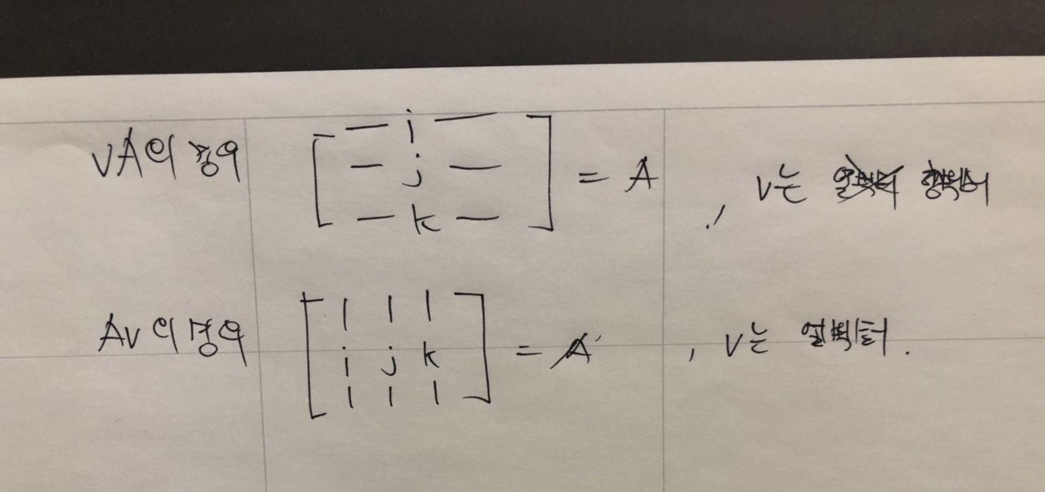
if the book uses column vector then vector multiplication with matrix is going to be Mv form which is below form in the above image.
Representation of basis vector i, j, k are also depends on the order of vector representation like the image I shown.
Sunday, February 9, 2020
Dynamic Bone
DynamicBone
초기 설정
루트로 설정한 게임 오브젝트의 자식들을 모두 순회하면서 파티클들을 등록한다. 여기서
사용하는 파티클이라는 용어는 물리를 적용할 요소를 뜻한다.
현재 게임 오브젝트의 월드 위치를 저장하고 부모에 상대적인 localPosition,
localRotation을 저장하고 있다. 이것들은 모두 m_InitLocalPosition, m_InitLocalRotation에 저장된다. 이 초기 위치와 회전들은 이후에 파티클들을 리셋 될 때 재사용된다. (물리
LOD가 적용되거나 특정 파라미터 값들이 수정되었을 때 리셋된다.)
물리 LOD
물리 시뮬레이션을 적용할 오브젝트가 지정된 오브젝트로부터 너무 멀리 떨어져 있으면 물리 시뮬레이션을 생략한다. 물리 LOD와 같은 개념이다.
UpdateDynamicBones(float
t)
이 함수에서는 주어진 시간 t동안 얼만큼 물리 시뮬레이션 돌려야 하는지
결정하고, 결정된 횟수만큼 물리 시뮬레이션을 돌린다. 이때
m_UpdateRate가 사용되는데 기본적으로 60으로 되어
있다. 1 / 60값으로 t를 나누어 얼만큼 물리 시뮬레이션
돌려야 하는지 결정하는데 이 횟수를 최대 3회로 제한한다.
횟수가 결정되고 나면 UpdateParticles1(),
UpdateParticles2()를 호출함으로써 물리 시뮬레이션 한다.
Verlet
적분
속도를 사용하지 않고 가속도와 이전 위치 만으로 다음 위치 값을 얻어낼 수 있는 방법.
xi+2=2xi+1–xi+aiΔt2
식에서 알 수 있듯이 현재 위치를 i+1이라고 하면 이전 위치 xi와 가속도 ai만으로 i+1의
다음 위치 i+2의 위치를 알 수 있다. DynamicBone은
이 방법을 사용해 물리 시뮬레이션 한다.
UpdateParticles1()
중력을 적용하고 (그런데 반대로 한다.) m_Force를 적용한다. (바람과 같은 힘을 적용하고 싶을 때
사용) 내부적으로 물리 시뮬레이션은 Verlet Integration을
사용한다. 모든 파티클들에 동일한 이동(루트 오브젝트의 이동)을 적용한다.
UpdateParticles2()
이 함수에서는 여러가지 작업을 차례차례 처리한다. 가장 먼저 기본
모양을 유지하는 코드가 있다. (keep shape 부분)
모양 유지
파티클의 초기 위치(로컬 좌표계에서의 위치)로부터 월드 공간에서의 위치를 얻고 restPos에 담는다. 그리고 restPos – p.m_Position을 통해 현재 파티클에서
초기 위치로의 방향을 얻는다. 이 벡터를 현재 파티클에서 m_Elasticity
비율값을 사용해 원래 위치로 돌아가는 처리를 진행한다.
한 가지 특별한 사항은 월드 공간에서의 위치를 얻기 위해 사용하는 행렬 m0을
사용할 때 위치 값을 아래와 같은 코드로 사용한다는 점이다.
|
m0.SetColumn(3,
p0.m_Position); // m_Position은 UpdateParticle1에서 업데이트 된 후의 월드 공간 위치
|
이것은 p0.m_Position 이며 UpdateParticle1 함수에서 업데이트 되고 난 후의 위치다. 현재
게임 오브젝트의 변환에는 아직 이동이 적용되지 않았으므로 이동을 업데이트하기 위해 SetColumn 함수를
사용해 이동을 업데이트 한다. 그 이후에 이 행렬을 사용해 자식 게임 오브젝트의 로컬 위치를 월드 공간으로
변환하여 restPos(되돌아갈 위치)를 얻는다.
충돌 처리
파티클의 이동에 있어 다른 오브젝트와 충돌 처리를 할 필요가 있다.
DynamicBoneColliderBase의 Collide 함수를 사용해 파티클 위치를
조정한다.
각 고정
물리 시뮬레이션은 특정 축에서만의 움직임으로 강제할 수 있다. 특별히
관심 있는 부분은 아니므로 생략.
거리 유지
|
Vector3
dd = p0.m_Position - p.m_Position;
float leng
= dd.magnitude;
if (leng
> 0)
p.m_Position
+= dd * ((leng - restLen) / leng);
|
파티클을 변환에 적용하기
파티클 업데이트에서 변경된 위치로 게임 오브젝트들의 위치를 업데이트 한다. 이때
사용되는 회전은 부모에서 자식의 방향으로 회전한다.
Subscribe to:
Comments (Atom)
-
 Unity released very good FPS example for people and I decided to analysis how they make this. Personally I wanted to show you how I analys...
 -
NSObjectCRuntime.h에서 오류가 나올 때 십중팔구 cpp파일의 속성을 objective c++로 설정하지 않아서 생기는 문제이다. 끝.
-
 For instance I have 45 degree rotation quaternion p. and if I take p ^ (1/3) then I'll get 15 degree rotation quaternion. This is geomet...